In this topic many ISSUES about REPAIR PDP and TFT (LCD) TV! 
Plasma Screen Panasonic TH-42PW6EXS
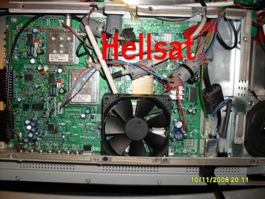
She came with a faulty power supply in the chain of five. As a stabilizer in this chain was used AN7705F. In view of his absence he was replaced by TDA8137 using 7yu leg as the output of +5.1 V, and the third and 4yu feet locked on the body. The difficulty was to replace the low voltage input voltage stabilizer (6.3 in). As the cooling was applied a small copper flazhek.

Had a few cases of LG panels with defective PDP2V6 CTRL, electronic malfunction on board were found, but replacement by another, the panel worked without problems .... After pereprogramirovaniya flashes, malfunction and gone. This firmware Logik - Firmware flush CTRL 6871QCH034A - 42V61EU1C (version). The firmware was read programmer with an adapter TSOP-48, with a new Logik-board. Certainly had some trouble, but at a ......
All broken CTRL pulled out of the panels are defective scans and killed Y-SUS, if the Y-SUS remained serviceable, Logik-Board did not suffer. But in the cases of murdered Y-SUS should not immediately plunge into a panic and buy a new CTRL 6871QCH034A or nothing pereprogramirovat. At 30 dead, Y-SUS affects approximately 2-3 CTRL. When dead Z-SUS or most panel firmware would not fly, in any case I have ever had more .... LG recommends replacement Logik scans for dead anyway, but I will say from experience that CTRL - not weak weak link in this system. Sometimes it helps to replace electrolytes and propayka. Vozni lot, but it also, and is .....
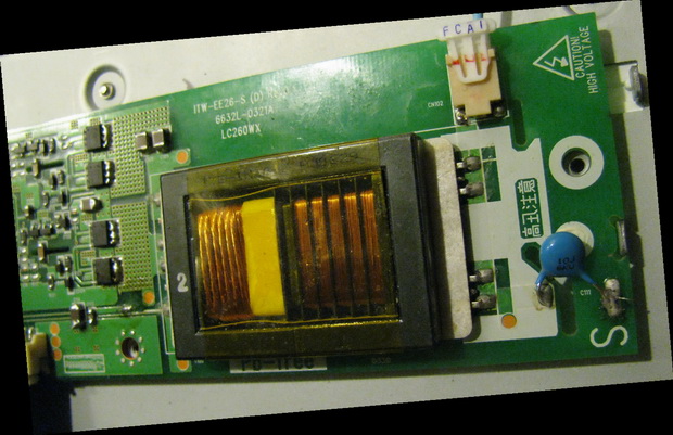
A bit of cooling scans and repairs and other fees. There's a lot to argue about whether you need to cool certain chips. If you listen to the advice of those who believe that all electronic components can withstand fairly large temperatutu at high loads and repeatedly tested at the factory, etc. Anything can and correctly. But practice shows something quite different. Many years have already been using the principle of cooling of parts and tell you, quite successful this occupation. Was used my will - open to new Appliances and rearranging them immediately. The most vulnerable spots PDP2V6 and similar models - a scan driver, after 2-3 years of work-SN755866 chip and thus similar to simply burn out and dragged into oblivion with a rather expensive fee Y-SUS (although not always, if a customer knew that include TV can not - then Y can be saved). Sami board drivers are not quite cheap and not every shop sells, it is necessary to patch .... Ideal - and acquire new board. If there is no possibility and means can be repaired old ones, especially all the chips do not burn at the same time as on some models, Samsung is going on. It is better to use the new SN755866, because donors were more likely overheated, overloaded, and their feeding of additional load (in addition to be 100% sure that the chip is in order, if it is closed - just goes down Y-SUS). Dead unsolder chips fairly easily, you can even akuratno cut all the legs of the soldering iron and heated from below (SN755866 soldered even lower to dissipate heat), remove the faulty mikruhu. I personally use hot air for desoldering. (Less fear that spoil the track). Pre-course we want to remove silicone, first coarsely (you can just nail), then soak it all in a solvent-based Nitro - Acetone, etc. (Careful with the solvent, many cards are connectors (plastic), for which the nitro - is death). Silicon becomes a kind of gelatin, soaked in water and easily removed with an old toothbrush. Another thing, if mikruha filled eboksitom, but it's a Samsung and this other time ... Landing site of course need to clean, remove excess tin Entlötlitze, copper network for sale now everywhere (otherwise it would be hard to put into place mikruhu), wipe the seat again for the disposal of fats, nitro, too, would go. After landing accurate solder mini-soldering iron on all sides by 3-4 feet, check with a magnifying glass is best symmetry. Then a large soldering iron to solder the chip down, here tin regret is not necessary, it is important to mikruha was soldered to the bottom, otherwise there will be heat on the board at the bottom and the legs of a lot of heat is not otvedesh. After already be soldered SN-ku minipayalnikom completely all 4 sides is desirable to have contact with each foot. for washing after soldering, I use the same nitro. At the bottom of the file added FD3284F (full Datashit unfortunately not yet, but the block diagram of the device can understand the principle of work). This is analogous to SN755866, noted that they are more reliable and durable in the work, but sales so far only available for manufacturers in the slats.
 Damp_CTRL.rar 17.1 KBDownload
fd3284f.pdf 64.97 KBDownload
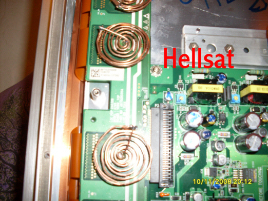
NA SN755866 chip in these models is almost impossible to stick heat-IT elements of aluminum or copper, because as Chip is a bar inside and between the panel and mikruhoy no room, and blow in this case is not very efficiently. The problem I decided to just. On the back pripaevaem for each SN-Ke copper wire thickness of about 1mm from it and wound spiral as in the photo. Efecta powerful - IC bask without blowing at 15-20% less. and to blow right by 50-60%. All this is taken not from the ceiling. Conducted experiments with measurements of temperature.
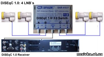
Most weaknesses (very warm themselves) is ckany, gibridka on Y-SUS and gibridka on Z-sus. In addition Mainboard (About the talk that stands alone) Grundig-Beko - the weakest point in these models. (Overheating, tap, flight software, etc.). That's why I posted a forced air cooling at these locations. Lyuftery desirable to take 120 mm for Y and Z Sus - s and 90mm for 8 Y51.190R-straining 12 volts. Large lyuftera less noisy than the small, but at the same time at lower bridle given to blow enough air. All the same, this is not a plane AN-24, a TV, so you should pay attention not only for cooling, but also the comfort cooling system. If you throw on lyuftera 12 V, I personally would not like to have a plane in the flat (me and the refrigerator in the kitchen enough). The voltage should be reduced to a minimum, approximately 5-6 volts, depending on the type lyuftera, then everyone can adjust the speed. But it is also important to lyuftera expected for 12 Volt free run (if napryazhemie very weak, there may be problems with running). All three lyuftera be powered from a separate power supply (I think this should not be here love to confess), after a relyushku. Where to connect relyushku - where there are 12 volts at the TV. I have a 12 in the audio of the power supply for Grundig-Mainboard. Load power supply himself three lyufterami should not be: a big load, and secondly lyuftera do sometimes go wrong, but samodelochny block at 12 - I think this is not a problem for the people of this forum. Photo attaching
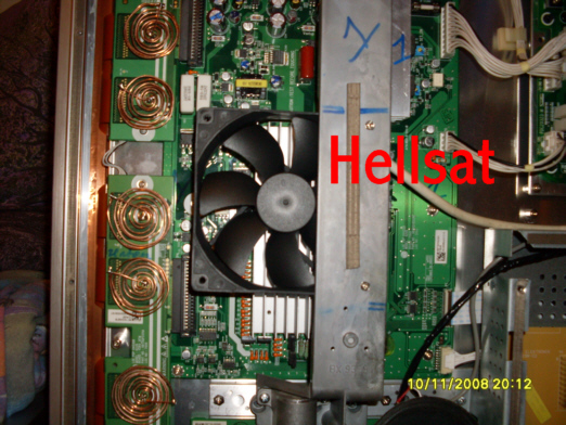
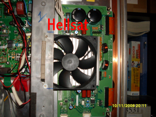
Takaya cooling system provides cooling of all components of the unit. Works no louder than the sound of the panel without audio sound. Blowing cool also blocks CTRL, the main power supply panel, power supply Grundig-Mainbord, as well. In order to save electric energy, can dream up and adjust the airflow depending on the temperature with sencorami, automatic starting and stopping, etc. But everyone can implement something of my own .......
About Grundig - Beko: The experience of recent years - it does not Grundig 80's and 90's. I had my way - would prohibit the release of all .... Interest around 80 I receive the repair models Grundig-Beko problem was not in the panels by LG and Samsung, as in the "washing" the panels in those "Grundikah and Beco"
Power supply - even where not kept, but the main board type Y51.190R-8 and such .... this is a real catastrophe ..... Of course I have no time to recoup flashes with each model with vypanivaniem. But one of the most problematic - will lay out here, because even the no interface and the original software from Grundig, a it is not pereprogramirovat after umertvleniya for one reason or another, it is not possible .... Sami boards are very sensitive on the subject of video processors, which can not be replaced. Prices for the full fee - space: from 350 - to 500 Euros. Here comes here to patch holes. Donors' I had this model for a lot, but all with a strange software. Conclusion: do not buy a Beko, and spent money on esche a programmer with adapters T-Sop 48, vypayal stick and read it with two models and preserved. Original software from Beko - in the Soviet Union easier camshaft on Zhiguli get!! In this way, restore or reconstruct a fairly decent amount Y51.190R-6 and Y51.190R-8 (differ only in software ).......
Note: Software versions of the boards Y51.190R - 6 to the panel 42 is not suitable, another scan, but her service menü change not only possible through intrefeys Grundig. (A is the image on the panel will not fit, but all else is working alone one)
Soft on Y51.190R-8 will put a little later, make out his archive first ....... somewhere lies silent ..... And another thing: Please note: we are not about Serial - eepromah with memory, but the Flash Type: 29LV800 - 29LV160 8 / 16 bit, it then lays the working software for the TV as a Windows PC to your hard drive. It is ridiculous of course can recall this, but I already asked the wizard who tried to somewhere in the 100-Gertsovom TV Sony, the main Flash programmed information of the channels tunera, or vice versa - in 24C16 tried to cram into the main software of the TV Sony, with a capacity exceeding a dozens of times ...... Generally Programming - a science separate ..........., but without it in the modern world is not enough
Info for AM29LV160 - Flash - memory is in many models Grundig - Beko, programiruesya programmer with an adapter
Type: T-Sop-48 / 8bit modus, T-sop48/16bit modus. Those who have no programmer and T-Sop48, but have experience pereprogramiryvaniya DVD-player based on chip MT8105 (or similar) and flash 29LV160-yourself interface and DVD_MTK_Tools just need to solder a chip pereprogramirovat necessary software, return to the place ..... for those who have Grundig - interface and the original software and programs, unsolder the chip needs only if he is dead or fully congregate software. In most cases, soldering is not needed ..........
Firmware for Y51.190R-8 Mainboard
Damp_Y51.190R-6.rar 330.2 KBDownload
damp_y51.190r-8_133.rar 334.36 KBDownload
am29lv160_pdf_677.rar 721.53 KBDownload
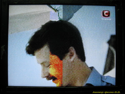
LCD Samsung Model: LE32R31SX/XES The client and take it under warranty, after two years with the problem: The sound is - the image disappears in different ways, or not appear at all, or we need to include a few dozen times so far appear izobrazhenie.ili disappears after 2-3 hours. In the studio said that replaced the LCD-Panel TV and returned back. I worked a couple of weeks, and again the same problem at this time the guarantee is over. Appliances fell into the hands of the master, who replaced the power supply to a new level for 250 Euro. TV worked for 3 weeks before returning to an old problem and came to the same master, this time was proposed replacement of the other charges 400 evro.Klient of course refused, bought a new one and this one dropped into the basement. I repaired it expensive SAECO coffee machine and a reward except for a payment received yet this TV for parts. I told him that I do not need it, your stuff know what to do, but look in terms of repair can try. And so the sound is there, the screen is dark. Opened, the type of saw nothing, he decided to drive, it's hard to start, but at the moment when something is measured like or do not turn on, or hours worked fine. All voltages are normal. He began to heat and cool everything, but found nothing. Propayal just in case Inverter Plata with transformers. Worked per week at my house and the old. Suspicions on Soft?? But he did not hurry up, driving as long as possible, checking the voltage on the inverters and one remarkable moment, said that the whole problem is sometimes with boards of inverters, and single-colored picture shows that something is illuminated sometimes not all right, it is clear that the illumination disabled, but because of what?? Examined all the platinum, all right, I have a donor search. Light plugs checked everything all right. Already quit this business like I suddenly noticed that the twitching cables illumination at the television, has emerged "problemka ours." It turned out one kabelek something quite finally otgorel. And this was that there is, no !!!!! From the factory they are welded to the lamps, but I did not disassemble the socket completely: cut out a little tin from the shell to get to the lamp cord cleaned, wrapped, soldered with tin, and 100% Ti did zazhimchik metallic copper. All closed, supplied inverter board first cooled from one lyuftera, put in place of his, drove a month a way and returned the master. Since then, working for a year without any problems. But every day with no problems encountered would love
LCD BBK LT3210S
Types of defects - bad loops with T-CONT in the matrix. Sprawled on the blades, while in the latter (repair) plume was no contact at 10-15 conclusions. Stsuko dumped six months after the epidemic of the shaft. At first did not understand, and threw him to the cancellation of such a defect of the matrix. And from Kiev assholes we began to fight.
In general, then:
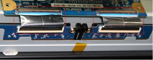
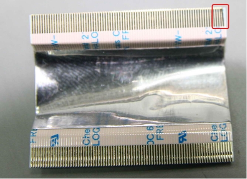
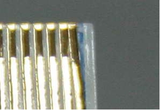
Bad shleyf.rar 650.41 KB Download
TFT-LCD HAIER L19C10A
TV did to malfunction -
a white vertical stripe on the right of the image.
The Matrix:
LTM190EX-L21 (
Samsung)
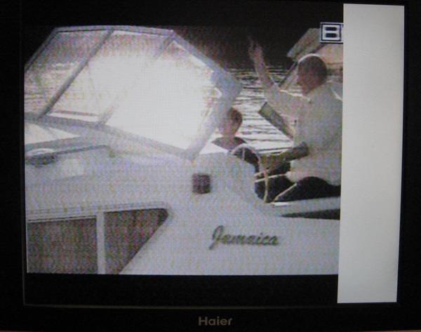
Away from the plume of the matrix to the board. To Restore pressed plume to the board clamp
resting on a rigid strip of foam rubber.
Samsung LE32AU51C1XRU
He entered with a diagnosis of "not out of the S-BY".
An autopsy showed that the main board does not come signal ON / OFF. The problem resolved Firmware Flash.
File attached.
T-CRL32PEUMD-1015 [1], [1] .0. Zip 843.57 KB Download
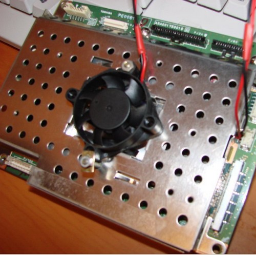
LCD Toshiba 37WL65R
Works 2-3 hours, then the image artifacts that occur in the form of strips, then squares the image. The board should RE0081 chip IC700 in which all image processing. Measurement of temperature showed that the chip is warmed up very strongly, about 80 degrees. Since heat sink was a sink of aluminum plate and pomernoy heat-conducting substrate, it was clear that it is necessary to improve cooling. I think that the reason that the substrate between the chip and heat sink, which is flat to impossible. In the end, smeared the chip heat-conducting paste, fins lowered and pressed to the chip. Installation of the cooler at 5 volts. Now working fine 
The pictures under the cooler radiator

LCD Samsung LW40A13W, chassis AL40AO.
Year of operation. External PSU. High-frequency noise from the TV, as well as noise from the speakers something like the rustle. The reason was swollen 1200mkf * 35B in BP. By the sound - in the piping IC13 TA1101B croaked Conder 1mkf * 25B, marking scheme C27, hence the noise in the speakers.
Inverter for LCD TV BIT3102A - a way to disable the protection.
I could not diagnose the defect known methods. We had to climb in the shield
BIT3102A - find a way otklycheniya protection. For inverters at BIT3102A = disable security setting on pin 6 voltage 2,5 V.
In my case it turned out - failure of two positions. This method helped them to locate.
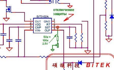
Heated ms PWM inverter circuit board and fuse burns FU2A to 12c. China.
I want to share my success, can someone come in handy. Orders inverter failed.
But the desire to revive the unit climbed a mountain, with success.
Okuratno, using a knife and cutting pliers, poizvraschalsya on-chip PWM inverter. It turned out that flew off
FET neizvesnoy brand. At his own risk (losing was not why) bought instrumentman IRF 640 and soldered them instead of the original (same pinout). Photo prikleplyayu. Polevik planted on the radiators, just in case. Run for 17 days without a break - flying Psychodelic_Creature.
AKAI LTA-26C903 Problem: after switching to dezh.rezhima screen zasvechivaetsya normally for 1-3 seconds. and goes, but the sound remains.
Almost immediately came to the inverters, as Team off to a procedure does not go, but he still stops working, the inverter is made up of two boards, which tore at different ends of the
TV, connecting train, went into denial fee, which is right, the signal ob.svyazi that came with it is not, of course when he ceased to go to train at the first substantive llatu, the protection is reset and it was a high-voltage disconnect samoproizvolno.prichinoy blue Conder in a rush to 10kvolt through it and shot ob.svyazi signal, the signal is passed it is not, has caught accidentally in the oscilloscope time otkaza.Mozhet to someone will help this case, and suddenly tipovuha?
just get better at Conder 10pik
6kvolt. the Photo he was well received

SONY KDL-40U2530. Malfunction - off every 1 sec ..
Learned from the client that he had included a power saving mode. The menu did not have time to go - had to short the resistor 6,8 Ohms 10 Watts at the time and in the menu to remove the regime. Also, due to the fact that this resistor was glued to the relay, the relay coil overheated and died. Relays for 18 Volt - put on 24 runs.
SAMSUNG LE46M87BD POWER BN44-00168. Chinese.
Problem - the sound is not running proofreader power, the output voltage corrector - 280 volts. Breaking track power PWM ICE1PC802 ICP801-DIP. It feeds on the winding PWM ICE3B0365J ICS801-DIP.
Track severed near the radiator CCM.
LCD SONY (, China without a model) 15 "- Matrix Samsung LTM15OXH-L06 - strip on the screen.
Error in the matrix.
That is a miracle! The owner says that the little boy screen washed with water, roll on the paint. The water probably came in the matrix. Question of the specialists of the matrices: a pipets or lechitsa? Appliances are not parsed by reason, and WMS Needless? So izvenyayus that the composition unspecified. If you want, correct it.

Ksati, circles visible and vyklyuchonnom too.

Source : http://monitor.espec.ws/section31/topic122783.html
TIP : Use Google Toolbar to translate language